
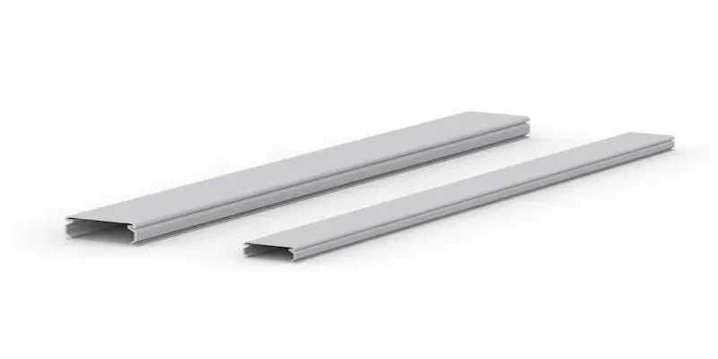
Exposed cords can make a workspace look unfinished, collect dust, create snag points, and make future cable changes harder to manage. Plastic molding for wire offers a simple way to route compatible cables along walls, desks, baseboards, and equipment surfaces while keeping the installation neat and accessible.
However, not every plastic channel suits every cable or location. The correct choice depends on cable type, channel capacity, bend radius, surface conditions, access needs, and local requirements. Buyers exploring workspace mounting and cable-management solutions should plan the complete route before choosing a size or installation method.
This guide explains how plastic wire channel systems work, where they can be installed, how to compare width and depth, and which mistakes to avoid. It is designed for facility managers, IT teams, office planners, installers, commercial buyers, and homeowners who want a safer-looking and more organized cable route.
What Is Plastic Molding for Wire?
Plastic molding for wire is a surface-mounted channel that covers and guides cables along a planned path. Most systems include a base that attaches to the surface and a removable or snap-on cover that conceals the cables.
Manufacturers may describe these products as plastic wire channel, PVC cable molding, cable cover molding, surface raceway, or cord cover. Although the terms often overlap, the products may not have the same rating, capacity, fittings, or approved uses. Always review the product documentation rather than relying on the name alone.
Cable Cover Versus Listed Raceway
A decorative cable cover may be intended only for low-voltage cords, communication cables, or preassembled power cords. A listed electrical raceway is designed and tested for specific wiring applications. Do not place building wiring or line-voltage conductors inside a channel unless the product is approved for that use and the installation follows applicable requirements.
When the project involves permanent electrical wiring, unfamiliar cable types, or a commercial installation, consult a qualified electrical professional before proceeding.
Benefits of Plastic Wire Molding
Plastic molding improves more than appearance. When selected and installed correctly, it can simplify cable routing and make the workspace easier to maintain.
- Cleaner presentation: The cover hides visible cables and creates a more consistent line along the mounting surface.
- Improved organization: Separate channels or divided raceways can help keep cable groups easier to identify and service.
- Reduced snag exposure: A covered route limits contact with loose cords in frequently used areas.
- Easier access: Removable covers allow authorized users to inspect, replace, or add compatible cables without opening the wall.
- Flexible routing: Elbows, tees, couplings, and end caps help the channel follow corners and transitions.
- Surface installation: Many systems avoid the disruption of cutting into finished walls, although the attachment method still requires planning.
These benefits depend on proper sizing. An overfilled channel can be difficult to close, may pinch cables, and leaves little room for future changes.
Where Plastic Cable Molding Can Be Installed
Plastic cable molding can work in offices, control rooms, classrooms, healthcare spaces, retail counters, home work areas, and light industrial environments. The surface, cable type, and exposure level determine whether a specific product is appropriate.
Walls, Baseboards, and Fixed Work Areas
Wall routes are useful when cables must travel between an outlet, network point, display, or workstation. Installers can also use molding near compatible wall-mounted systems to guide power and data cables toward the equipment without leaving long loops exposed.
Baseboard placement can reduce visual impact, but the route must avoid doorways, heat sources, moisture, sharp edges, and areas where the molding may be struck.
Desks and Adjustable Workstations
A fixed channel can organize cables along the rear or underside of a desk. However, height-adjustable furniture needs extra cable length and a controlled movement path. When planning cable routing for office standing desks, keep the stationary molding separate from the flexible cable section that moves with the desktop.
The same principle applies to monitor arms. A wall or desk channel can guide cables toward the arm, but the final section must allow the display to extend, rotate, and tilt without pulling the connectors.
Mobile and Track-Mounted Equipment
Permanent wall molding should not restrict equipment designed to move. For computer carts, route cables on the cart itself and maintain safe connection points rather than creating a fixed path that limits mobility.
Likewise, equipment installed on track mounting systems needs enough flexible cable to travel across the intended adjustment range. The molding should end before the moving section begins.
How to Select the Correct Width and Depth
Choosing a channel by outside dimensions alone can lead to an undersized installation. Compare the usable internal area, not just the overall width and depth shown on the package.
List Every Cable
Record each cable that will enter the molding. Include power cords, network cables, USB cables, audiovisual connections, control wiring, and any adapters that must pass through the route. Note the largest connector because it may require a wider opening than the cable itself.
Allow Space for Bends and Future Changes
Cables should not be forced into tight corners or compressed under the cover. Leave enough space to preserve the recommended bend radius and to remove individual cables later. A small amount of spare capacity also makes future additions easier.
Check Fittings and Transitions
The straight channel may have enough capacity while an elbow, tee, or outlet box becomes the limiting point. Confirm that every fitting supports the planned cable bundle and that connectors can pass through required openings.
Consider Segregation Requirements
Some applications require power and low-voltage cables to remain separated. A divided channel or separate runs may provide a clearer layout, but the exact approach depends on the cable types, product listing, and applicable requirements.
How Plastic Molding Protects and Organizes Cables
Cable cover molding creates a physical boundary around the cable route. It can reduce direct contact with cords, keep bundles aligned, and limit movement caused by cleaning or routine workspace activity.
Still, plastic molding does not make cables immune to damage. The channel should not cross areas with vehicle traffic, repeated impact, high heat, standing water, corrosive exposure, or other conditions beyond the product’s rating.
Use Logical Cable Groups
Group cables according to their destination and service needs. For example, a display route may include power and signal connections, while a workstation route may serve a computer, phone, and network connection. Labels at entry and exit points can make future troubleshooting faster.
Control Entry and Exit Points
Use suitable end caps, bushings, or transitions where cables enter and leave the channel. The cable should not rub against a sharp cut edge. In addition, leave enough slack to connect equipment without placing tension on ports or plugs.
Preserve Ventilation and Access
Do not route molding across ventilation openings, service panels, removable covers, or control labels. Keep the path accessible so technicians can open the channel without removing unrelated equipment.
How to Cut and Fit Plastic Wire Molding
A clean installation starts with accurate planning. Read the manufacturer’s instructions first because cutting tools, fastening methods, fitting sequences, and minimum temperatures can vary by product.
- Plan the complete route. Mark the start, end, corners, branches, and equipment connection points. Confirm that the path avoids moving parts, doors, heat, and moisture.
- Measure each straight section. Measure twice and account for couplings, elbows, end caps, and device boxes before cutting the channel.
- Cut the base and cover cleanly. Use the tool recommended for the material. Support the molding during the cut to reduce cracking or distortion.
- Smooth the cut edges. Remove burrs that could interfere with the cover or damage the cable jacket.
- Dry-fit every section. Assemble the route without cables first so you can verify alignment, fitting placement, cover clearance, and access.
- Attach the base to a clean, suitable surface. Use the approved adhesive, fasteners, or combined method. Adhesive-backed products still require a sound, clean surface and may not suit every material.
- Place cables without twisting or overfilling. Maintain appropriate bends and confirm that cables remain free at moving equipment connections.
- Install the cover and test the equipment. Check that every cover closes fully, each connection remains secure, and the complete route stays clear of movement and service areas.
When cutting around corners, rely on compatible fittings rather than forcing the molding to bend. Purpose-built elbows and transitions usually produce a cleaner route and protect the cables more effectively.
Installation Mistakes to Avoid
Most cable-molding problems begin during planning. Avoiding the following mistakes can improve appearance, accessibility, and long-term performance.
- Choosing a channel that barely fits the current cable bundle.
- Ignoring connector size, bend radius, or the capacity of corner fittings.
- Using a decorative cord cover for wiring applications it is not approved to support.
- Installing over dusty, damp, textured, damaged, or incompatible surfaces without preparation.
- Relying on adhesive where mechanical fastening or a different product is required.
- Routing across access panels, ventilation openings, doors, drawers, or moving equipment paths.
- Stretching cables tightly between the channel and adjustable equipment.
- Mixing incompatible cable types without checking separation requirements.
- Leaving sharp cut edges or unsupported gaps at entry and exit points.
- Failing to label cable destinations before closing the cover.
Final Planning Checklist
Before installation, confirm the cable type, internal channel capacity, fitting sizes, route clearance, surface condition, attachment method, and equipment movement. Also verify that the chosen product is suitable for the environment and intended wiring application.
The best plastic molding for wire is not simply the narrowest or least visible option. It should provide enough capacity, protect the cable path, allow future service, and fit the workspace without restricting equipment.
For help planning cable routing around wall-mounted, adjustable, or mobile equipment, contact a mounting specialist to discuss the workspace, equipment configuration, and installation goals.
Frequently Asked Questions
What is plastic molding for wire used for?
It conceals and organizes compatible cables along walls, desks, and equipment surfaces while keeping the route accessible for inspection or changes.
Can cable molding be used for electrical wiring?
Only use a product approved for the specific wiring application. Permanent or line-voltage work may require a listed raceway and qualified installation.
How do I choose the right cable molding size?
List every cable and connector, then choose a channel with enough internal space for safe bends, easy closure, service access, and future additions.
Will adhesive cable molding stick to any wall?
No. Adhesion depends on the surface, preparation, environment, and product instructions. Textured, dusty, damp, or damaged surfaces may need another method.
Can plastic cable molding go around corners?
Yes. Use compatible inside corners, outside corners, elbows, or flexible fittings instead of forcing straight molding into a sharp bend.